


Guitar wiring basics, part one
This is about connecting together the pieces that make an electric guitar. There are a lot of sites that cover all the details about one or two specific types of guitars, but if you're not using the exact guitar they're talking about those sites aren't much help. And even the more general sites seem to lack the most basic starting points about how the parts work together.
This first page about wiring covers the basics of basics. It starts with directly attaching a pickup to an amplifier and progresses to connecting a split-coil humbucker in 4 steps.
All you need to know to follow this article is what a pickup is and what switches do. There are a couple of ways of drawing switches, so let's get that out of the way. (This does not count as one of the 4 steps, if you're keeping track.)
It's time to switch
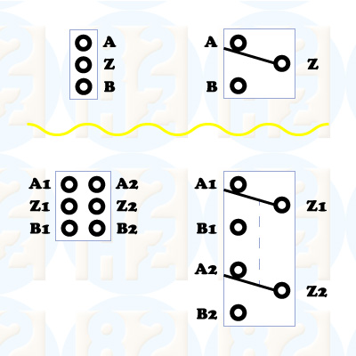
The most basic switch we're interested in is called SPDT. It means that one signal can be connected to either of two places, and it's shown in the upper portion of the "Switch types" diagram. Sometimes it is easier to show a circuit using the symbol shown on the left, such as in wiring diagrams, but the diagram on the right is the type to use as the circuits get more complicated. The both try to provide the same information.
The SPDT switch will connect Z to either A or B. Usually that's all you need to know about it, but there are two variations that add a center position. That position will either connect Z to both A and B or connect Z to nothing.
The bottom part of the diagram show a DPDT switch. It acts like two SPDT switches that are physically connected together. For example, in one position Z1 connects to A1 and Z2 connects to A2. None of the items connecting to the -1 parts have any electrical connections to the -2 parts.
These can keep growing to add more connections in any direction. For example, what is often called a three-way switch would be like the SPDT, but it would allow Z to connect to either A, B or C.
The three-way switches in guitars make the new connection before breaking the old one, aka make before break. Because you can stop the switch in between the final positions there are really five states that a three way switch can be in.
| Position | Connection |
|---|---|
| 1 | A |
| 2 | A & B |
| 3 | B |
| 4 | B & C |
| 5 | C |
The ease of getting a switch to stay in positions 2 or 4 depends on the switch construction.
Picking up the pace
Starting from zero, we work our way to a split-coil pickup connetion.
In the beginning…
The first electric guitar probably looked like Figure 1.
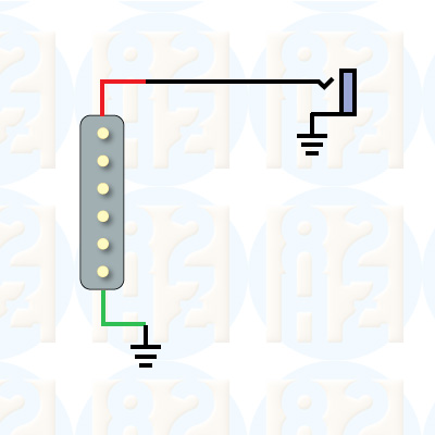
They took a guitar, clamped the pickup that had magically appeared (next to a cable and Marshall stack) into the big empty spot under the strings and connected it all together.
Stating the (hopefully) obvious, in these figures the rectangle with the six circles is a pickup, and the thing to the right represents a standard jack that you would plug your cable into.
The thing with three horizontal lines is a ground symbol, and all of those symbols should be considered as connected together. Using ground symbols can make the diagrams easier to follow because it lowers the number of crossing connections.
For the most part, ignore the line/wire colors in all of the diagrams. I'll let you know if it's important, but different pickups use different colors, so in general discussions like this just ignore it.
Turn that down…
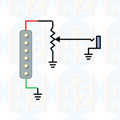
The first electric guitar was most likely modified to look like Figure 2 soon after it was created to solve the problem of the first audience yelling, "Turn that thing down!!!" Fortunately, a potentiometer was in the pile of things that had appeared next to the amplifier. And now the first guitar had the first volume control.
If one was good…
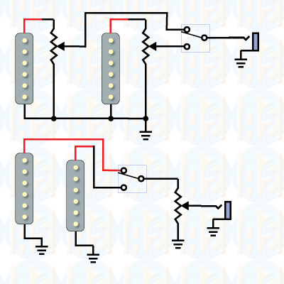
We know what a switch does and we have a volume control so let's do it twice and use the switch to select which pickup to use. Although there are a few other ways to connect two pickups, this diagram shows the most common basic concepts. One option is to wire the pickups to the switch and then use a single volume control. The other is to give each pickup its own volume control.
Remember how I described that some switches have a middle position that can make Z connect to either both A and B or to neither? Guitar switches usually have the mid-postion that connect Z to both A and B. So now with one switch you have 3 options: pickup 1, pickup 2 or both.
And finally…
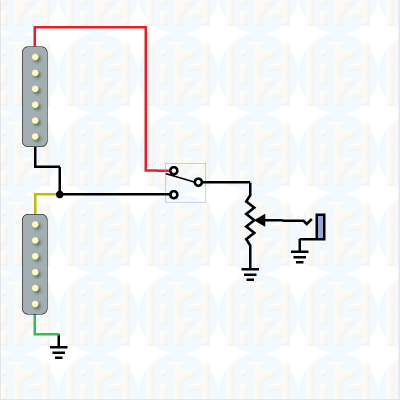
A humbucking picking is really two pickups in one package. Factory stock often doesn't give any access to where the two connect to each other, but after-market pickups do. That's what is happening in this diagram: the connetion between the two pickups is going to one side of the switch. Note how similar this is to the bottom of Figure 3.
This configuration gives a standard humbucker when the switch is in the top position and a single-coil pickup in the bottom position. In this type of wiring, the center position isn't used because it would act the same as the bottom position.
Wrap-up
This went from the basic connection of a single pickup to a split-coil humbucking configuration in four steps, as promised. All that's missing from this is a tone control, and you'll have the wiring that can be used on many single-pickup guitars.
Adding a tone control will be covered in the next article on pickup wiring.